Identify the physical switch configuration necessary to support a given AOS networking feature
3-Tier Network Architecture
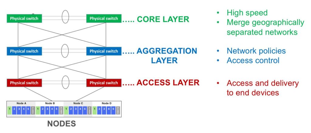
Core layer
- Considered the backbone of networks
- Largest, fastest, yet also most expensive routers
- Used to merge geographically separated networks
- Purpose: Move data across network at highest possible speed
Aggregation (aka Distribution) layer
- Located between access and core layers
- Purpose: provide boundary definition by implementing access lists (filters)
- Defines policy for the network
- Includes high-end layer 3 (routing) switches
- Ensures proper routing of packets between subnets and VLANs
Access layer
- Access and delivery to end devices (computers, printers, servers etc)
Leaf-spine Architecture
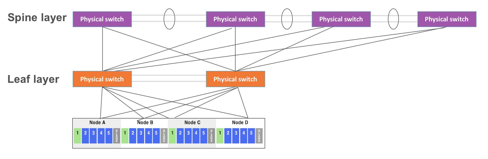
Leaf-spine topology adds switches at the layer below the access layer, and then spread the links from the access layer to the next, across the network. A leaf-spine design scales horizontally through the addition of spine switches, which spanning-tree deployments with a traditional three-layer design cannot do.
With leaf-spine, access and aggregation layers are widened. A host can talk to another host on any other leaf switch and know that the traffic will only traverse the ingress leaf switch, spine switch and egress leaf switch. As a result, applications running over this network infrastructure will behave predictably.
However, a high (leaf) switch count is necessary to scale up to support all physical hosts. The larger the number of leaf switches needed to uplink all of the physical hosts, the wider the spine needs to be to accommodate them, which translates into significant cabling requirements and associated cost.
Also, a spine can only extend to a certain point before either the spine switches are out of ports and unable to interconnect more leaf switches, or the oversubscription rate between the leaf and spine layers is unacceptable. In general, a 3:1 oversubscription rate between leaf and spine layer is deemed acceptable.
For example, 48 hosts connecting to the leaf layer at 10Gbps use a potential maximum of 480Gbps. If the leaf layer connects to the spine layer using 4 40Gbps uplinks, the interconnect bandwidth is 160Gbps, for an oversubscription ratio of 3:1.
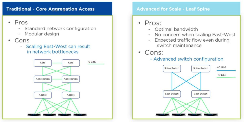
Switch Topology Comparison
In most scenarios Core-Agg will work fine for small-medium-large business. The primary case where Leaf-spine matter are data centers of scale where 100+ hosts are used and need to intercommunicate.
Also for a more expected traffic flow. If you want to take a switch down for maintenance and you are running an L3 protocol, attributes can be adjusted so that no traffic is using the switch prior to maintenance. This is much harder in a standard L2 environment.
Improving performance
Easy ways to ensure performance
- Spanning-tree PortFast on host to switch configured
- Line rate, non-blocking switches with no oversubscription – cut-through good, do not use store and forward i.e. dont use FEX!
- Faster link speeds 1gig vs 10gig vs 40gig – recommend faster!
Advanced configurations
- Pinning traffic for east-west optimization
- Data locality means we already optimize how much network bandwidth we need to consume for storage I/O, however in the event maintenance or potential failure we need to ensure sufficient bandwidth can support these scenarios.
- Jumbo frames configuration
- Discouraged for distributed systems like Nutanix except for external/iSCSI based clients. Do I need it? 95% of customers do not use it!
- Static/LACP Port-channels
- Multi-switch link aggregation (MLAG/vPC)
- Use an Ethernet switch that has a low-latency, cut-through design and that provides predictable, consistent traffic latency regardless of packet size, traffic pattern, or the features enabled on the 10 Gb interfaces. Port-to-port latency should be no higher than two microseconds.
- Do not trunk switch ports that connect to the IPMI interface. Configure the IPMI switch ports as access ports for management simplicity.
- Use redundant top-of-rack switches in a leaf-spine architecture. This simple, flat network design is well suited for a highly distributed, shared-nothing compute and storage architecture.
- Add all the nodes that belong to a given cluster to the same layer-2 network segment.
Load Balancing
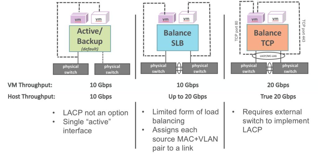
Balance-slb
SLB bonding allows a limited form of load balancing without the remote switch’s knowledge or cooperation. Bonding allows two or more interfaces to share network traffic.
From a high-level point of view, bonded interfaces act like a single port, but they have the bandwidth of multiple network devices, e.g. two 10 GB physical interfaces act like a single 20 GB interface. Bonds also increase robustness: the bonded port does not go down as long as at least one of its interfaces is up.
SLB assigns each source MAC+VLAN pair to a link and transmits all packets from that MAC+VLAN through that link. Learning in the remote switch causes it to send packets to that MAC+VLAN through the same link.
By default, the interfaces are rebalanced every 10 secs. To rebalance, vswitchd examines the statistics for the number of bytes transmitted by each interface over approximately the past minute, with data sent more recently weighted more heavily than data sent less recently.
Balance-tcp
Requires the external switch to implement LACP, but it is otherwise very simple in that, after LACP negotiation is complete, there is no need for special handling of received packets. ALWAYS configure the switch for LACP first, then place the Nutanix bridge/bond in Balance-TCP mode.
More information about Bond Options can be found here.